Architecture#
Class Diagram#
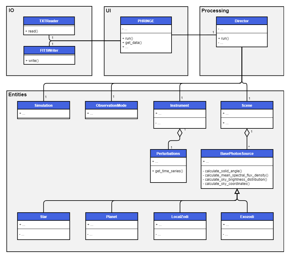
The simplified class diagram of PHRINGE shown below gives an overview of the software architecture. The key components are a user interface (UI), a processing component, an input/output (IO) component and the entities.
Components#
UI#
The UI contains the PHRINGE class, which serves as an interface to let the user configure the simulation and retrieve the results thereof.
Processing#
The processing component contains the Director, which is responsible for coordinating the simulation. This includes the following steps:
Calculate the symbolic instrument response.
Calculate the simulation time steps.
Calculate the field of view of the observatory.
Calculate the nulling baseline.
Calculate the instrument perturbation time series, if applicable.
Calculate the spectral flux density, brightness distributions and coordinates of all sources in the scene.
Calculate the differential counts using the intensity response and the sources in the scene.
IO#
The IO component contains the TXTReader and ``FITSWriter``classes to read text and write FITS files.
Entities#
The entities are the classes that represent the objects in the simulation. The main objects are the Simulation, ObservationMode, Instrument and Scene classes.